Modular HVAC system simulation and test.
Define how the compressors respond, assemble the modular HVAC plant, and verify the integrated system with Plant Test. Connect external controllers when testing the complete command-and-feedback loop.
Define compressor behavior.
Establish the equipment response that the plant simulation will use.
- Define
- Select the compressor family, model, refrigerant, and behavior mode. Review load response, operating limits, and available curve or recorded-log inputs.
- Validate
- Check startup, loading, unloading, stopping, and fault/reset response. Compare capacity, speed, pressures, temperatures, and electrical input with the intended operating envelope.
- Save
- Retain model settings, edited curves, and source logs with the engineering baseline. Include the selected compressor configuration when saving the System Integration project.
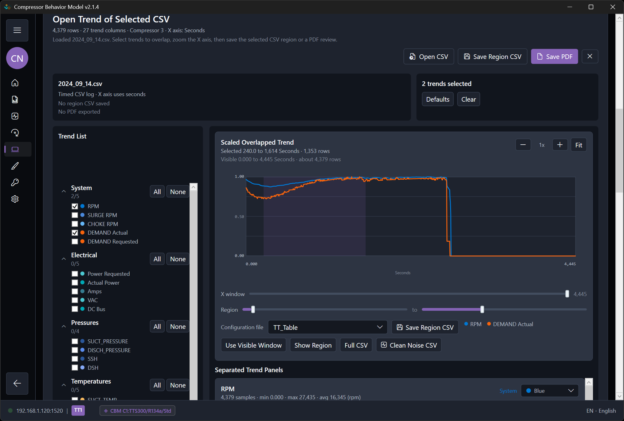
Integrate the modular HVAC system.
Connect equipment behavior, mechanical topology, and control interfaces in one system project.
- Define
- Compose compressor groups, refrigerant circuits, water loops, economizers, pumps, and towers. Connect I/O and editable Signal Logic; assign external PLC interfaces through endpoints, Unit IDs, and register maps.
- Validate
- Apply the topology to the draft, compile it, and review connections, units, point mappings, and output ownership. Explicitly activate the approved system before running its Plant Test.
- Save
- Save one portable .modbussim project with the shared System design, equipment configuration, topology, mappings, logic, behavior assets, and current Plant Test scenario. Opening or editing a draft does not activate it.
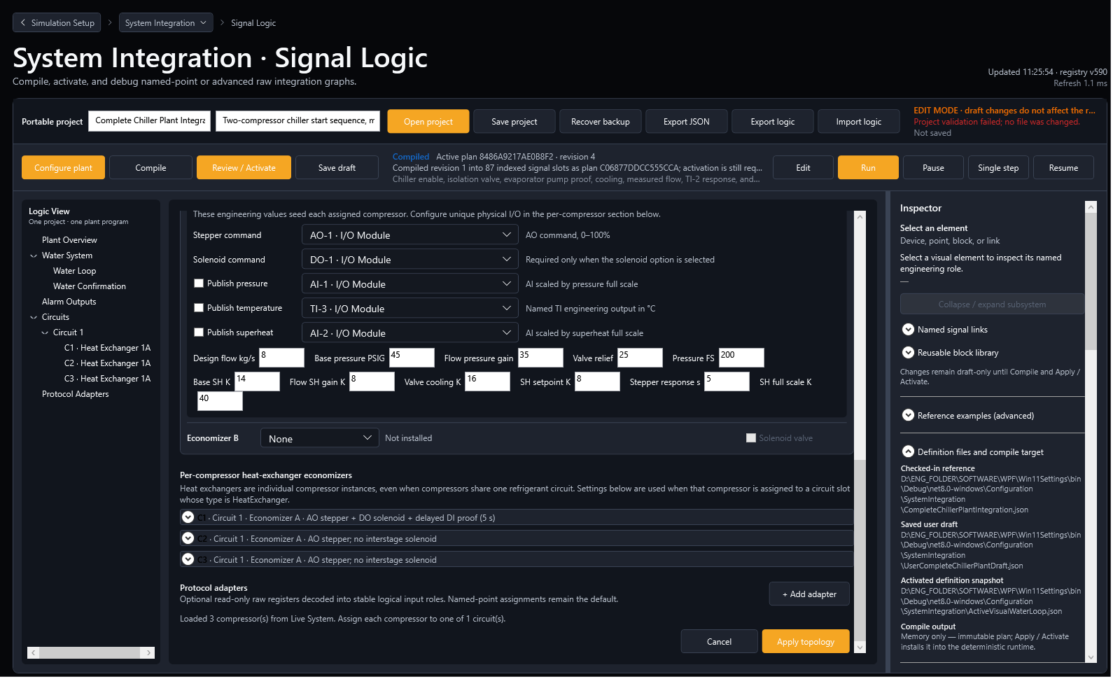
Test the plant against engineering criteria.
Use the Plant Test scenario stored with the active system project to check performance, protection, and recovery.
- Define
- Enter the shared System design in Configurator. Plant Test inherits it; then add timed Step or Ramp phases, mapped stimuli, measurable acceptance criteria, and Alarm/Fault Injection scenarios when abnormal conditions are part of the test.
- Validate
- Confirm the intended project is active and required communications are running. Execute the test, compare trends and response timing with the criteria, and review Passed, Failed, Incomplete, or Not exercised results.
- Save
- Save the updated Plant Test scenario in the same portable .modbussim project. Standalone .modbustest files remain import-compatible; complete evidence folders and reports stay separate from the project file.
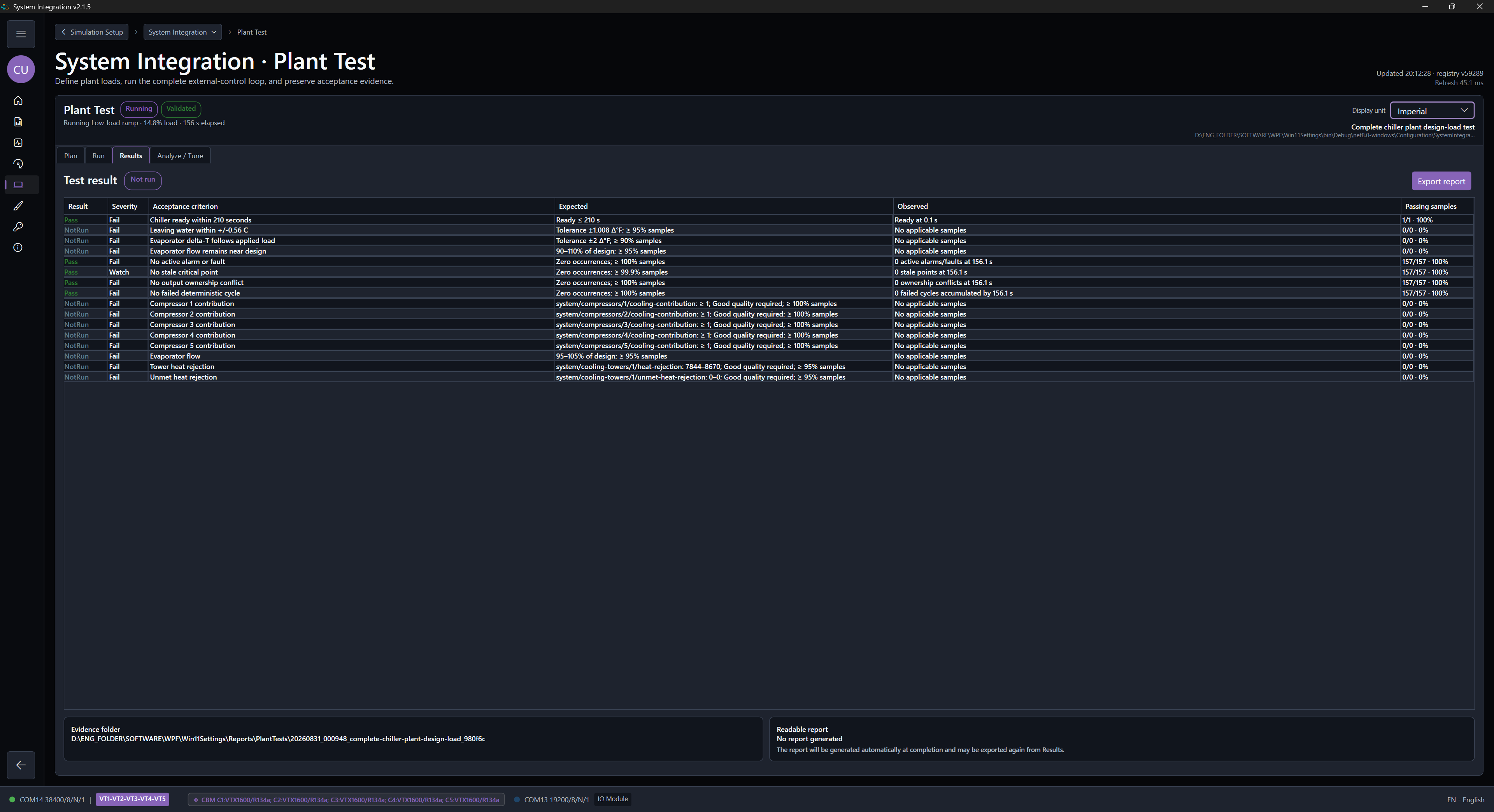
Alarm / Fault InjectionCompressor points, power, water flow, and deliberate communication-error scenarios.
Test runs saved fault scenarios in prepared projects. Creating or editing scenarios requires Engineering, or Starter for learning and evaluation.
Target a compressor point, equipment, supply group, adapter, or endpoint. Run one manual event or save coordinated scenarios in the active project's Plant Test scenario.
- Compressor points and indications
- Change supported pressure, temperature, or current inputs with entry, hold, and return timing; assert supported alarm or fault bits.
- Power and backup supplies
- Model outages, capacitor/UPS/battery autonomy, controller boot delays, and restart permission for selected equipment or supply groups.
- Water flow and proof
- Reduce evaporator or condenser physical flow, or fail the flow-proof indication while retaining the modeled thermal flow.
- Communication errors and disturbance
- Inject complete or targeted response loss, delay, jitter, Modbus exceptions, and explicit write-loss behavior while non-targeted units remain available.
Check detection, timing, and recovery.
Set an independent response, a detection deadline, and a recovery window. Review per-event verdicts, actual event markers, response and power traces, raw observations, and printable reports. Applied does not mean Passed.
Reports describe simulator observations. Field-controller behavior still requires a test with that controller.
Read the injection workflowPlant Test Analyze / TuneStudy completed evidence and prepare a separate tuning draft.
Analyze captured behavior before changing the simulation.
Load completed Plant Test evidence, verify deterministic replay, compare bounded parameter candidates, and inspect capacity, controller, thermal, and refrigerant response. The study never edits or activates System Integration. Intentional fault runs remain diagnostic evidence and are excluded from normal-operation calibration and tuning validation.
Evidence-only analysis · physical and conservation checks remain hard gates · draft-only handoff
Analyze / Tune guide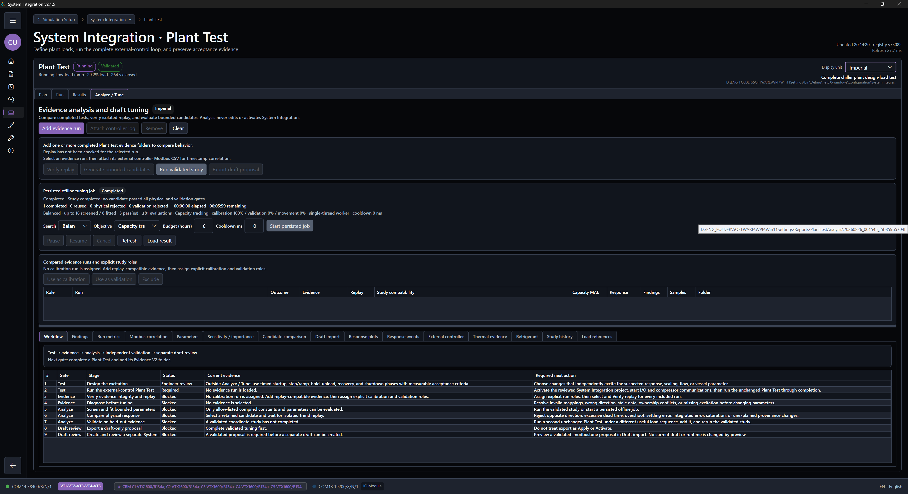
Move from product understanding to action.
Request the installer, follow the guides, or review licensing.